

BNWAS (Bridge Navigational Watch Alarm System)
The bridge navigational watch alarm system (BNWAS) monitors bridge activity and detects operator disability that could lead to marine accidents. The Watch Keeper monitors the awareness of the Officer Of the Watch (OOW) and automatically alerts the Master or another qualified person if for any reason the OOW becomes incapable of performing the OOW's duties. This process is subdivided in different alarm stages which primarily try to alert the OOW via visual and audible alerts.

 Bridge Navigational Watch Alarm System (BNWAS)
In case the Watch Keeper Alarm does not receive any evidence of life, the alert will be transferred to the selected backup Officer Of the Watch (OOW) cabin(s). Assuming that no acknowledgement has been triggered either, the ultimate alert stage will activate alarm devices in public area. Additionally, the Bridge Watch Alarm provides the OOW with a means of calling for immediate assistance if required (emergency call).
- intuitive and comfortable use on bridge
- compact connecting module picks-up all periphery equipment
- easy to install
- 100% compatible with Stein Sohn BNWAS A006.3 / A006.5 / A006.6 (exisiting wiring and periphery can be used)
- modern control philosophy with rotary encoder allows to check all connected devices and links
- NMEA expansion module available
- MED Type Approved (wheel marked)
- IEC 62288 Ed. 2.0 (2014-07)
- IEC 62616(2010) incl. IEC 62616 Corr. 1 (2012)
- IEC 60945 (2002) incl. IEC 60945 Corr. 1 (2008)
- IEC 61162-1 ed4.0 (2010-11) and ed5.0 (2016-08)
- IEC 61162-2 ed1.0 (1998-09)
- IEC 62923-1/2
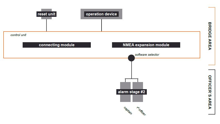
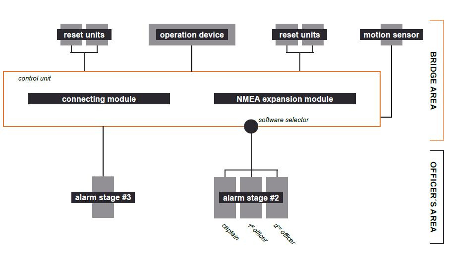
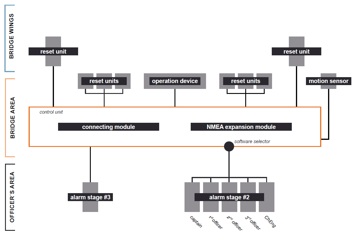
System overview for different vessel size
BNWAS system for small vessel (minimal recommended system composition)
BNWAS system for medium vessel size
BNWAS system for large vessel size
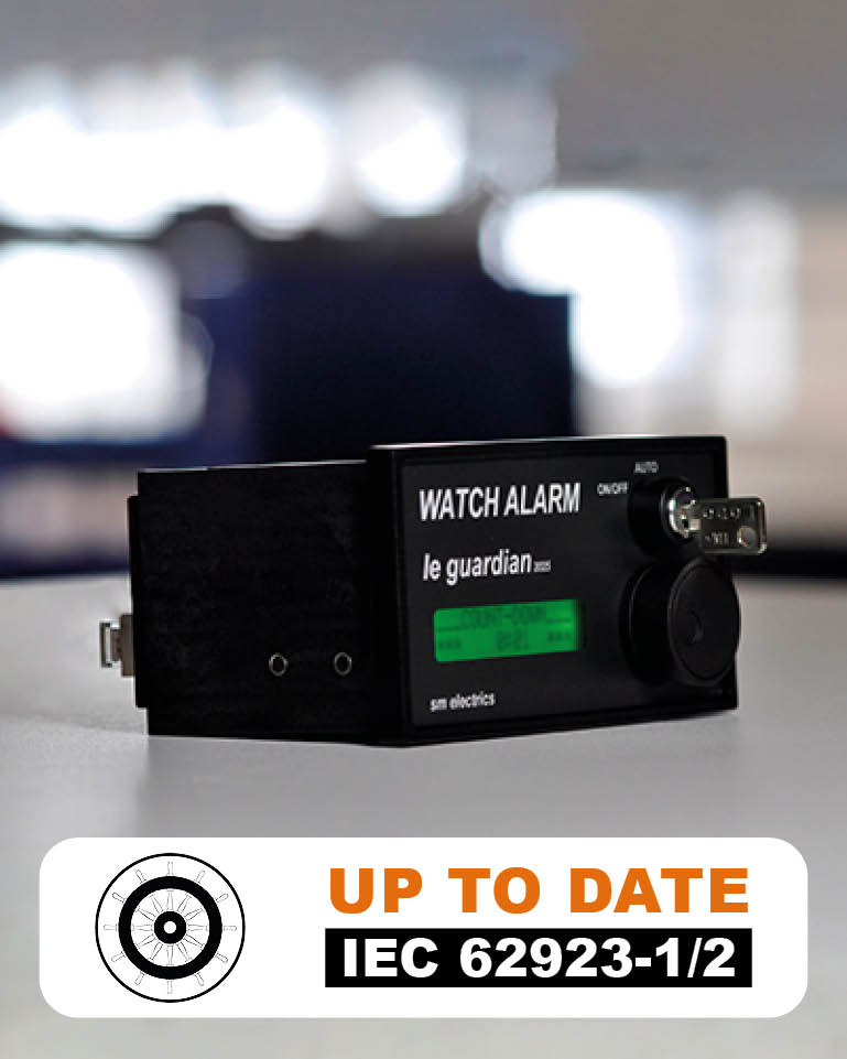
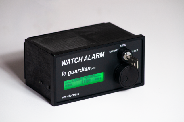
Nostalgic Story about our BNWAS le guardian 2025
It has been created at a Sunday’s breakfast table some months before the SMM 2008 and it is showing the 1st draft of our hot selling BNWAS operating device. Inspired by the home micro-wave’s operation philosophy with a simple rotary encoder and a double lined and coloured display, the system should be initially called “the guardian 7475” in the style of the lovely “the Conells” song ’74 ’75. But legal issues have been feared and the idea has been cancelled by the family council after heated debate. The 2nd best market name won the race, and the system has been called “le guardian 2025”, bringing additional int’l flair into the story. 2025 should represent the system’s state-of-the-art technology for the next two decades…
Did it come true?
Did it come true?
Imagination

Reality
Why is a BNWAS (Bridge Navigational Watch Alarm System) so important?
At first sight a BNWAS system seems like a millstone around the neck, as it just generates noise and disturbes the watchkeeper. But when it comes to one person watchkeeping and fatigued watchkeepers watchkeeping on navigation bridges, it is the only way to ensure a safe operation of the vessel. A very interesting articel of marine insight shows three differnent incidents, where a BNWAS system could have helped to avoid the incidents.

